Enhanced TDS
Knowde-enriched technical product data sheet
Identification & Functionality
- Chemical Family
- Fillers Included
- Polymer Name
- Plastics & Elastomers Functions
- Technologies
- Product Families
Features & Benefits
- Materials Features
- Thermocomp™ Compounds For Dielectric Solutions
LNP™ THERMOCOMP compounds portfolio contains thermoplastic injection molding materials that offer low Dissipation Factor (Df ) for improved signal gain and longer reading distance paired with tailor made Dielectric Constants (Dk ) to fine tune or detour a signal direction supporting innovative antenna designs. Beyond that, THERMOCOMP compounds allow further antenna miniaturization and the design of phase shifters with higher productivity through combined high Dk and low Df material properties.
Typical Industry Requirements
- Materials for individual antenna design to fine tune or detour signal direction.
- Improved signal gain and longer reading distance through less signal attenuation.
- Miniaturized antenna solutions with sufficient signal strength for 5G technology.
- Improved mechanical performance versus Epoxy or Ceramics in more complex designs for less maintenance through longer lifetime.
Typical Material Characteristics
- Tailored Dielectric Constant Dk by customized compound formulations.
- Very low Dissipation Factor Df for lower signal absorption, less signal scattering.
- Combined high Dk and low Df with very high signal transmission density.
- Sufficient flowability for thin wall design, improved ductility, dimensional and dielectric stability versus current solution.
Applications & Uses
- Markets
- Applications
- Plastics & Elastomers End Uses
- Plastics & Elastomers Processing Methods
Properties
- Physical Properties
Value Units Test Method / Conditions Melt Volume Rate (at 190°C, 10.0 kg) ¹¹ 7.5 cm³/10 min ISO 1133 Melt Volume Rate (at 220°C, 10.0 kg) ¹¹ 12.5 cm³/10 min ISO 1133 Mold Shrinkage (flow) ᵍ ¹¹ 1.5 - 2 % SABIC method Density ¹¹ 2.5 g/cm³ ISO 1183 Water Absorption (at 23°C, 24hrs) ¹¹ 0.08 % ISO 62-1 - Mechanical Properties
Value Units Test Method / Conditions Tensile Stress (Break, 5 mm/min) ¹¹ 20 MPa ISO 527 Tensile Strain (Break, 5 mm/min) ¹¹ 1.2 % ISO 527 Tensile Modulus (at 1 mm/min) ¹¹ 2550 MPa ISO 527 Flexural Stress (Break, 2 mm/min) ¹¹ 15 MPa ISO 178 Flexural Modulus (at 2 mm/min) ¹¹ 2750 MPa ISO 178 - Thermal Properties
Value Units Test Method / Conditions Coefficient of Thermal Expansion (at 23°C to 60°C, flow) ¹¹ 0.00013 1/°C ISO 11359-2 Coefficient of Thermal Expansion (at 23°C to 60°C, xflow) ¹¹ 0.00015 1/°C ISO 11359-2 Heat Deflection Temperature/Bf (at 0.45 Mpa, Flatw 80*10*4, sp=64mm) ¹¹ 100 °C ISO 75/Bf Heat Deflection Temperature/Af (at 1.8 Mpa, Flatw 80*10*4, sp=64mm) ¹¹ 60 °C ISO 75/Af - Electrical Properties
Value Units Test Method / Conditions Dissipation Factor (at 100 MHz) ¹¹ 0.009 - IEC 60250 Dissipation Factor (at 500 MHz) ¹¹ 0.008 - IEC 60250 Dissipation Factor (at at 1 GHz) ¹¹ 0.008 - IEC 60250 Relative Permittivity (1 GHz) ¹¹ 13.1 - IEC 60250 Relative Permittivity (100 MHz) ¹¹ 13.6 - IEC 60250 Relative Permittivity (500 MHz) ¹¹ 13.4 - IEC 60250 - Impact Properties
Value Units Test Method / Conditions Izod Impact (Unnotched, 80*10*4, at 23°C) ¹¹ 5.5 kJ/m² ISO 180/1U Izod Impact (Notched, 80*10*4, at 23°C) ¹¹ 3.5 kJ/m² ISO 180/1A - Injection Molding
Value Units Test Method / Conditions Drying Temperature ⁷ 80 °C - Drying Time ⁷ 4 Hrs - Maximum Moisture Content ⁷ 0.03 % - Melt Temperature ⁷ 210 - 215 °C - Front - Zone 3 Temperature ⁷ 205 - 215 °C - Middle - Zone 2 Temperature ⁷ 200 - 210 °C - Rear - Zone 1 Temperature ⁷ 190 - 200 °C - Mold Temperature ⁷ 15 - 55 °C - Back Pressure ⁷ 0.2 - 0.3 MPa - Screw Speed ⁷ 30 - 60 rpm - - Note
- ᵍ Measurements made from Laboratory test Coupon. Actual shrinkage may vary outside of range due to differences in processing conditions, equipment, part geometry and tool design. It is recommended that mold shrinkage studies be performed with surrogate or legacy tooling prior to cutting tools for new molded article.
- ⁷ Injection Molding parameters are only mentioned as general guidelines. These may not apply or may need adjustment in specific situations such as low shot sizes, large part molding, thin wall molding and gas-assist molding.
- ¹¹ The information stated on Technical Datasheets should be used as indicative only for material selection purposes and not be utilized as specification or used for part or tool design.
Technical Details & Test Data
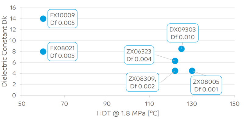
- Typical Properties of Thermocomp Compounds for Dielectric Solutions

Packaging & Availability
- Country Availability
- Regional Availability