Enhanced TDS
Knowde-enriched technical product data sheet
Identification & Functionality
- Chemical Family
- Reinforcement Material
- Composite Materials Functions
- Technologies
- Product Families
Features & Benefits
- Materials Features
- Product Highlights
AD1000 is a high dielectric constant substrate that permits circuit miniaturization, compared to traditional low loss materials. It is especially beneficial for power amplifiers, filters, couplers and other components using low impedance lines. AD1000 is a woven glass reinforced laminate. This allows for Greater Dimensional Stability and Mechanical Robustness than other 10 Dk Products. Its large panel size is also advantageous for “multi-circuits per panel” processing. AD1000 is considered a “soft substrate” and is relatively insensitive to vibrational stress. This allows miniaturized circuitry without requiring the complicated processing or special handling associated with brittle pure ceramic or ceramic hydrocarbon materials. AD1000 is compatible with processing used for standard PTFE based printed circuit board substrates. In addition, the low Z-axis thermal expansion provided by the ceramic loading will improve plated through hole reliability, compared to typical PTFE based laminates. The low X-Y thermal expansion provides excellent matching to ceramic chip carriers and other ceramic components. AD1000 was specifically developed for Miniaturized Circuitry for compact devices (i.e., GPS Receivers), Patch Antennas (where smaller size is required), Satellite Communications Systems, Power Amplifiers (PAs), Low Noise Amplifiers (LNAs), Low Noise Block Downconverters (LNBs), Radar Modules and Manifolds, Aircraft Collision Avoidance Systems (TCAS), and Ground Based Radar Systems.
- Features
- Only Woven Glass Reinforced PTFE/ Ceramic with Dk of 10.2 or greater
- Thermal Conductivity is “Best-in-Class”
- High copper peel strength allows for thinner etched line widths
- Lowest Insertion Loss Available
- Larger Panel Sizes Available
- Low Moisture Absorption
- Excellent CTE Values lead to highly reliability ceramic component attachment and PTH reliability
- Benefits
- Mechanically Robust
- Greater Dimensional Stability than Other 10 Dk Products
- Circuit Miniaturization Leads to Weight Savings
- Heat Dissipation and Management
- Greater Signal Integrity
- Cost-Effective Board Layout and Board Processing
- Low Loss in Humid Environments
Applications & Uses
- Markets
- Applications
- Recommended Applications
- Ideal for X-Band and Below
- Radar Modules and Manifolds
- Aircraft Collision Avoidance Systems (TCAS)
- Ground Based Radar Surveillance Systems
- Miniaturized Circuitry & Patch Antennas
- Power Amplifiers (PAs)
- Low Noise Amplifiers (LNAs)
Properties
- Typical Properties
Value Units Test Method / Conditions Dielectric Constant at 10 GHz 10.2 - IPC-TM-650 2.5.5.5 Surface Resistivity (E24/125) 3.16 x 10^8 MΩ IPC-TM-650, 2.5.17.1 Dissipation Factor tan d, at 10 GHz 0.0023 - IPC-TM-650 2.5.5.5 Surface Resistivity (C96/35/90) 1.8 x 10^9 MΩ IPC-TM-650, 2.5.17.1 Thermal Coefficient of εr -380 ppm/°C IPC-TM-650 2.5.5.5 Volume Resistivity (E24/125) 5.36 x 10^7 MΩ-cm IPC-TM-650, 2.5.17.1 Volume Resistivity (C96/35/90) 1.4 x 10^9 MΩ-cm IPC-TM-650, 2.5.17.1 Electrical Strength 24.5 kV/mm IPC TM-650 2.5.6.2 Dielectric Breakdown min. 45 kV IPC TM-650 2.5.6 Arc Resistance min. 180 seconds IPC TM-650 2.5.1 Td, Initial min. 500 °C IPC TM-650 2.4.24.6 Td, 5% min. 500 °C IPC TM-650 2.4.24.6 T260 min. 60 min IPC TM-650 2.4.24.1 Time to Delamination (T288) min. 60 min IPC TM-650 2.4.24.1 T300 min. 60 min IPC TM-650 2.4.24.1 Thermal Expansion, CTE (x,y) 50-150ºC 8, 10 ppm/°C IPC TM-650 2.4.41 Thermal Expansion, CTE (z) 50-150ºC 20 ppm/°C IPC TM-650 2.4.24 Peel Strength to Copper after thermal stress 2.1 N/mm IPC TM-650 2.4.8 Peel Strength to Copper at elevated temperatures 2.4 N/mm IPC TM-650 2.4.8.2 Young’s Modulus 200 kpsi IPC TM-650 2.4.18.3 Flexural Strength 9.9/7.5 kpsi IPC TM-650 2.4.4 Tensile Strength 5.1/4.3 kpsi IPC TM-650 2.4.18.3 Compressive Modulus min. 425 kpsi ASTM D-3410 Poisson’s Ratio 0.16 - ASTM D-3039 Water Absorption 0.03 % IPC TM-650 2.6.2.1 Density 3.2 g/cm3 ASTM D792 Method A Thermal Conductivity 0.81 W/m/°K ASTM E1461 Outgassing Total Mass Loss 0.01 % NASA SP-R-0022A Outgassing Collected Volatile Condensable Material 0 % NASA SP-R-0022A Outgassing Water Vapor Recovered 0 % NASA SP-R-0022A
Technical Details & Test Data
- Dielectric Constant vs. Frequency
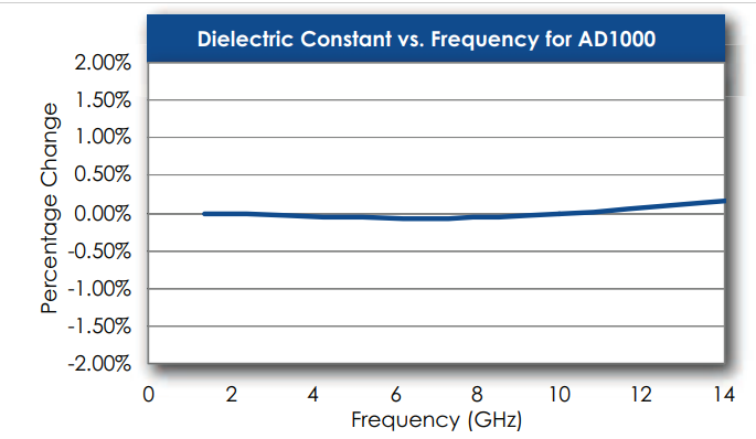
Demonstrates the Stability of Dielectric Constant across Frequency. This information was correlated from data generated by using a free space and circular resonator cavity. This characteristic demonstrates the inherent robustness of Arlon Laminates across Frequency, thus simplifying the final design process when working across EM spectrum. The stability of the Dielectric Constant of AD1000 over frequency ensures easy design transition and scalability of design.
- Dissipation Factor vs. Frequency
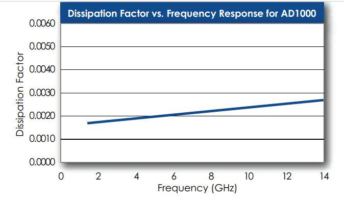
Demonstrates the Stability of Dissipation Factor across Frequency. This characteristic demonstrates the inherent robustness of Arlon Laminates across Frequency, providing a stable platform for high frequency applications where signal integrity is critical to the overall performance of the application.
Packaging & Availability
- Material Availability
AD1000 laminates are available in a range of thicknesses from 0.020” to 0.127” (and beyond). AD1000 is supplied with 1/2, 1 or 2 ounce standard or reverse treat electrodeposited (ED) copper on both sides. Other copper weights and rolled copper foil are available. AD1000 is available bonded to heavy metal ground planes. Aluminum, brass or copper plates also provide an integral heat sink and mechanical support to the substrate. Other combinations of thickness and cladding may be available. Contact Arlon with any requests for nonstandard materials. When ordering AD1000, please specify thickness, cladding, panel size, and any other special considerations. Standard panel sizes include: 18” x 24”, 12” x 18” and 16” x 18”. Contact Arlon Customer Service for other panel sizes.